# Layer Refinement
Layer Refinement defines automatic mesh snapping and refinement for layered structures.
This object corresponds to tidy3d.LayerRefinementSpec (opens new window).
Layer refinement is useful for RF layouts where thin conductor or dielectric layers need controlled resolution along the layer normal direction. It can also align grid cells with important stack-up interfaces, layer bounds, and in-plane corners.
# Name
name: Unique name for the layer refinement.
- Required field
# Geometry
The refinement region can be created from nets, from layers, or from an explicit geometry.
# Nets
nets: Net objects used to define the refinement region.
- Required field when creating from the Nets tab
When one or more nets are selected, the layer refinement geometry follows the bounding box of the selected nets.
# Layers
layers: Layer objects used to define the refinement region.
- Required field when creating from the Layers tab
When one or more layers are selected, the layer refinement geometry follows the bounding box of the selected layers.
# Convert to Center and Size
convert to center and size: Convert the selected nets or layers into an explicit center and size definition.
This option applies only to geometry created from selected nets or layers. Use this option to convert the geometry to the center/size definition for manual adjustment.
WARNING
The conversion to the center/size definition is non-reversible. To revert back to the layer- or net-based definition, please create a new LayerRefinementSpec.
# Center + Size
Object definition through a center position and size.
center: Center of the refinement region in x, y, and z-directions.
- Type: floating-point number
- Unit: m, mm (default unit), um
size: Size of the refinement region in x, y, and z-directions.
- Type: floating-point number
- Unit: m, mm (default unit), um
- Constraint: greater than or equal to 0
- Required field
# Bounds
Object definition through minimum and maximum coordinate bounds.
min: Values of the x, y, and z coordinates defining the lower corner of the refinement region.
- Type: floating-point number
- Unit: m, mm (default unit), um
- Required field
max: Values of the x, y, and z coordinates defining the upper corner of the refinement region.
- Type: floating-point number
- Unit: m, mm (default unit), um
- Required field
# Refinement Along Normal Axis
axis: Layer normal axis.
- Options: X/Y/Z
- Required field
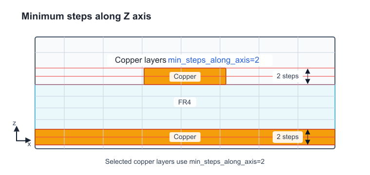
min_steps_along_axis: Minimum number of grid steps across the layer thickness.
- Type: floating-point number
For axis = Z, layer-normal refinement is applied through the z direction. For example, min_steps_along_axis = 2 creates at least two grid steps across each selected copper layer thickness, while dielectric layers can remain on the default grid.
# Bounds Snapping
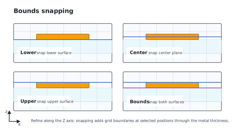
bounds_snapping: Toggle whether grid boundaries are snapped to a position along the layer normal axis.
- Options:
- True: Add a snapping position along the layer normal axis.
- False: Do not add a bounds snapping position.
type: Position used for bounds snapping.
- Options: Lower/Center/Upper/Bounds
- Default: Center
For axis = Z, bounds snapping aligns z grid boundaries with selected positions through the layer thickness.
# Bounds Refinement
bounds_refinement: Toggle whether the mesh is refined around the lower and upper layer bounds.
- Options:
- True: Refine the mesh around the layer bounds using grid refinement settings.
- False: Do not add bounds refinement.
When enabled, bounds_refinement uses Grid Refinement settings.
# Refinement Along In-plane Axes
For axis = Z, these controls refine gaps and corners in the XY plane.
# Gap
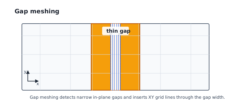
gap_meshing_iters: Number of recursive iterations used for resolving thin in-plane gaps.
- Type: integer
dl_min_from_gap_width: Toggle whether detected gap width contributes to the suggested minimum grid size.
- Options:
- True: Use detected gap width when determining the local minimum grid size.
- False: Do not use detected gap width for the local minimum grid size.
# Corner
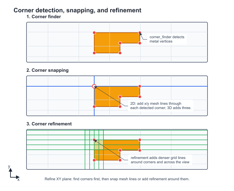
Corner detection settings define which in-plane geometry corners are detected before corner snapping or corner refinement is applied.
See Corner Finder Specification.
corner_finder: Toggle whether in-plane corners are detected for snapping and refinement.
- Options:
- True: Detect corners on the plane perpendicular to the layer normal axis.
- False: Do not detect corners.
- Default: True
corner_snapping: Toggle whether grid boundaries are snapped to detected in-plane corners.
- Options:
- True: Snap grid boundaries to detected corners.
- False: Do not add corner snapping points.
- Default: True
corner_refinement: Toggle whether the mesh is refined around detected in-plane corners.
- Options:
- True: Refine mesh around detected corners using grid refinement settings.
- False: Do not add corner refinement.
- Default: True
When enabled, corner_refinement uses Grid Refinement settings.
# Advanced
refinement_inside_sim_only: If structures extend outside the simulation domain, the LayerRefinementSpec can generate refinement based on structural features outside the simulation domain. Use this control to toggle whether refinement is limited to structural features only within the simulation domain.
- Options:
- True: Generate refinement based on structural features inside the simulation domain only.
- False: Allow refinement based on structural features outside the simulation domain also.
- Default: True
interior_disjoint_geometries: Toggle handling of disjoint interior geometries.
- Options:
- True: Include disjoint interior geometries in layer refinement handling.
- False: Do not include disjoint interior geometries.
NOTE
Layer refinement is applied through the grid specification and is used when at least one grid direction uses AutoGrid or QuasiUniformGrid.