# Lumped Port
A Lumped Port represents a rectangular port used to excite and measure a terminal between 2 metallic structures.
This object corresponds to tidy3d.rf.LumpedPort (opens new window).
# Name
name: Unique name for the port.
- Required field
# Geometry
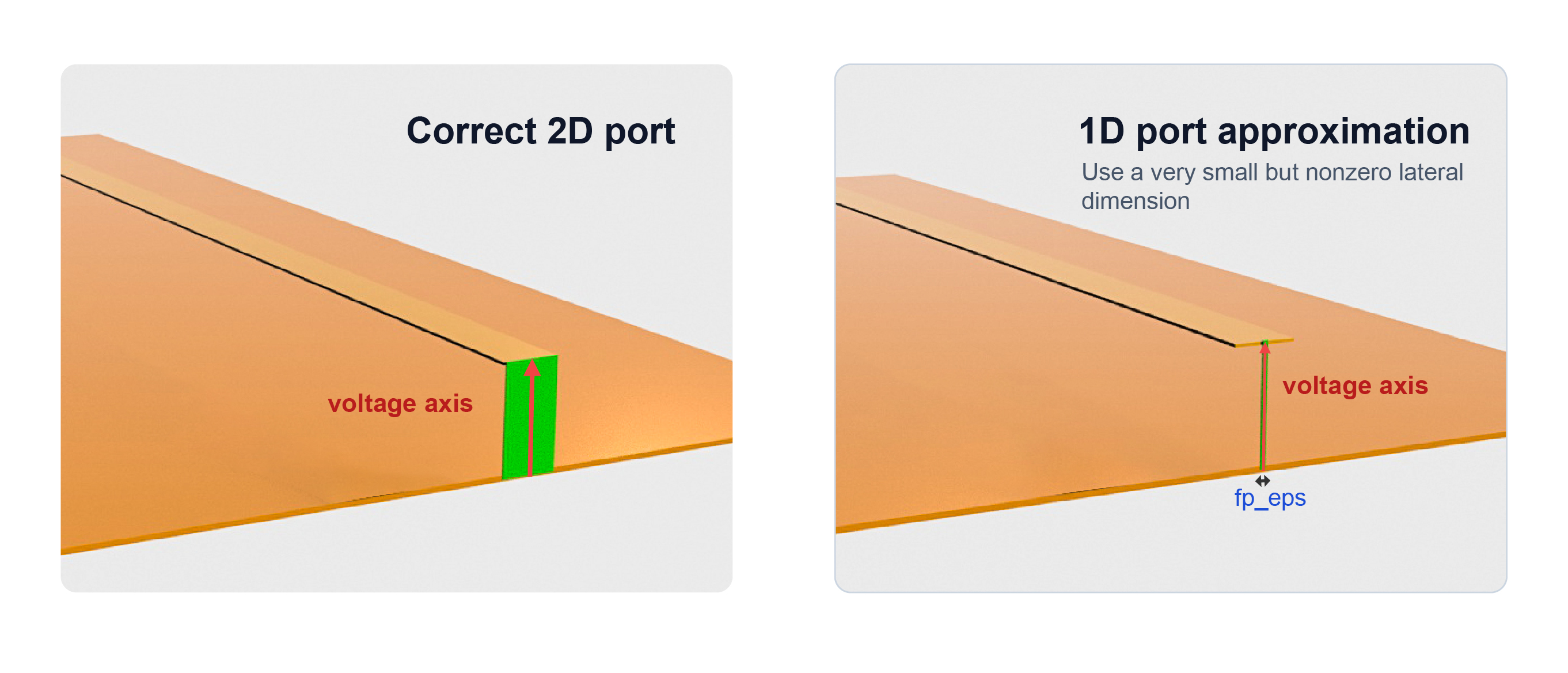
Specification of the lumped port region. The port is a rectangular box. In a typical RF setup, one dimension is set to 0 so that the port lies on a plane between a signal and a reference or ground.
NOTE
True one-dimensional ports, with two zero-size dimensions, are not supported. To approximate a 1D port, keep the normal dimension at 0 and set one lateral dimension to a small but finite value, such as fp_eps 1e-6.
# Center + Size
Object definition through a center position and size.
center: Center of the port in x, y, and z-directions.
- Type: floating-point number
- Unit: m, mm (default in the RF GUI), um, or other available length unit
size: Size of the port in x, y, and z-directions.
- Type: floating-point number
- Unit: m, mm (default in the RF GUI), um, or other available length unit
- Constraint: greater than or equal to 0
- Required field
# Bounds
Object definition through minimum and maximum coordinate bounds.
min: Values of the x, y, and z coordinates defining the lower corner of the port.
- Type: floating-point number
- Unit: m, mm (default in the RF GUI), um, or other available length unit
- Required field
max: Values of the x, y, and z coordinates defining the upper corner of the port.
- Type: floating-point number
- Unit: m, mm (default in the RF GUI), um, or other available length unit
- Required field
# Settings
# Voltage Axis
voltage_axis: Axis along which the electric field line integral is performed when computing the port voltage. The voltage axis must lie in the plane of the lumped port.
- Options: X/Y/Z
- Required field
NOTE
Set the voltage axis direction based on the direction of the physical voltage drop between terminals.
# Impedance
Reference port impedance used for scattering parameter computation.
real: Real part of the reference impedance.
- Type: float number
- Unit:
- Default: 50
imag: Imaginary part of the reference impedance.
- Type: float number
- Unit:
- Default: 0
# Advanced
# Distribution Type
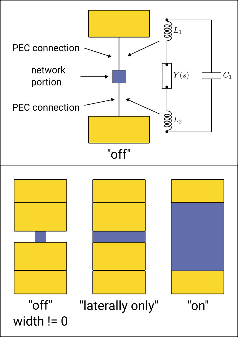
dist_type: Distribution type used by the lumped element that models the port load.
- Options:
- On: Distribute the network portion of the lumped port, including the source, across the full lumped element bounding box.
- Off: Restrict the network portion to one grid cell and use PEC connections to connect that cell to the edges of the lumped element.
- Laterally only: Distribute the network portion only along the lateral axis of the lumped port.
- Default: On
NOTE
Use On for most RF layouts. Use Off or Laterally only only when the network should not be distributed over the full bounding box, since the PEC connections can introduce additional parasitic series inductance and shunt capacitance.
# Mesh
num_grid_cells: Number of mesh grid cells associated with the port along each direction. These cells are added through automatic mesh refinement. Increasing this value refines the mesh around the port and can improve port voltage/current accuracy at the cost of a larger simulation.
- Type: integer
- Constraint: greater than 0
- Default: 3
snap_perimeter_to_grid: Toggle whether the perimeter of the port is snapped to the simulation grid. The lumped port is always snapped along its injection axis. This option controls snapping of the in-plane port perimeter.
- Options:
- True: Snap the port perimeter to the grid to improve accuracy when the element contains a small number of grid cells.
- False: Do not snap the port perimeter to the grid.
- Default: True
enable_snapping_points: Toggle whether snapping points are automatically generated at key geometric features of the lumped port.
- Options:
- True: Generate snapping points for more accurate modeling.
- False: Do not generate snapping points.
- Default: True
NOTE
Keep snap_perimeter_to_grid and enable_snapping_points enabled for most RF layouts, especially when the port spans only a few grid cells.